
Hotdisplay Technology Co., Ltd
HOTDISPLAY's capacitive touch product information includes structures such as G+G, G+F, G+FF, P+G and P+F. The appropriate construction depends on the required mechanical design and selected product.
Confirm the controller IC and communication interface, such as I²C where specified. The touch interface is not necessarily the same as the display interface, so both must be checked against the host board.
Selected products support cover-glass customization, including shape, thickness, printed borders or logos and surface treatments. The design must match the front-panel opening and visible area.
Options listed for selected products include AG anti-glare, AR anti-reflection and AF anti-fingerprint treatments. Select according to lighting, reflections, fingerprints and cleaning requirements.
Depending on the selected touch panel or TFT assembly, customization may include:
Cover-glass dimensions, thickness, contour and cut-outs.
Printed border color or logo.
Touch-panel structure and selected controller options.
FPC cable length, position, pinout and connector method.
Surface treatment and transmittance requirements.
Evaluation of display-and-touch compatibility.
These options are subject to the selected model and technical feasibility. For custom development, provide a mechanical drawing and clearly identify the required visible window, cover outline and touch-control interface.
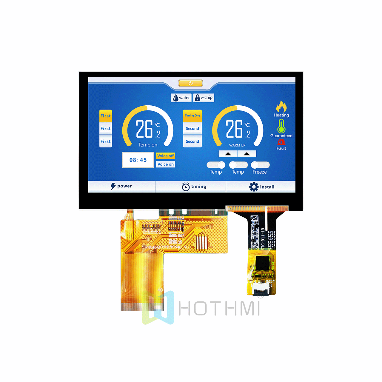
TFT capacitive touchscreens are used in:
industrial HMIs
smart home appliances
medical and measurement equipment
handheld instruments
interactive terminals and other electronic products that require direct screen interaction.
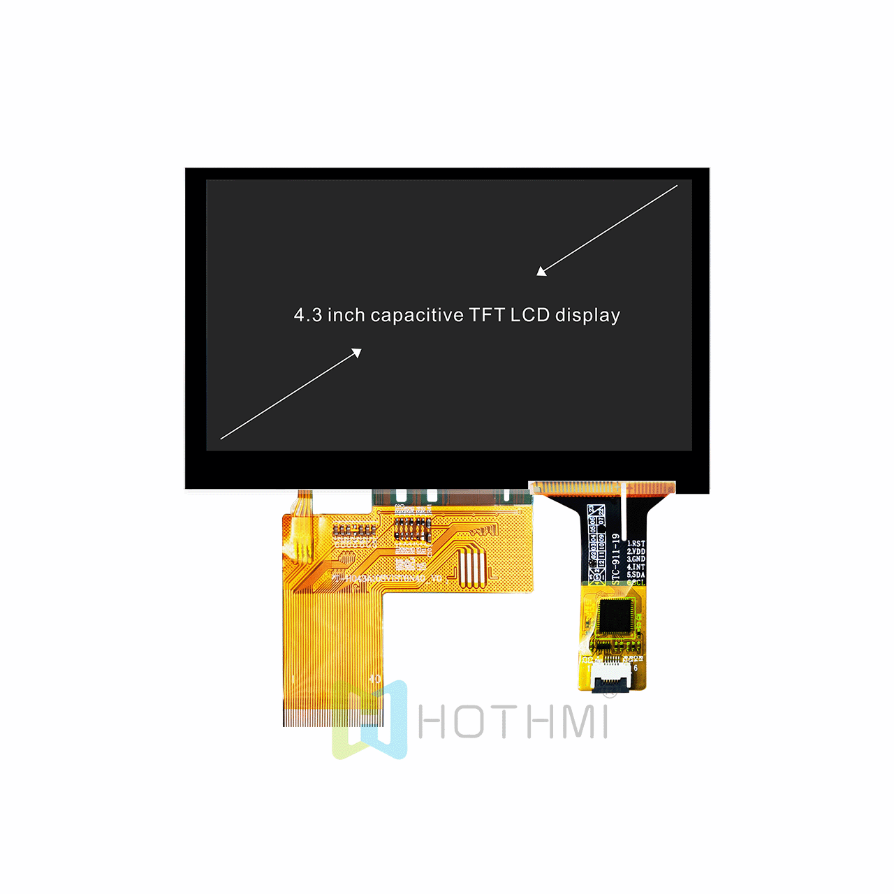
Do not assume multi-touch: Confirm the supported number of touch points and controller capability.
Do not ignore cover thickness: Confirm that the chosen touch design supports the planned cover.
Do not confuse touch and display interfaces: Verify the controller and pinout for each.
Do not finalize the front panel too early: Confirm cover dimensions, active area, printed border and openings.
Do not assume all coatings are interchangeable: Choose AG, AR or AF according to the actual optical and usage requirements.
Do not assume optical bonding is included: Confirm the quoted assembly structure and bonding scope.
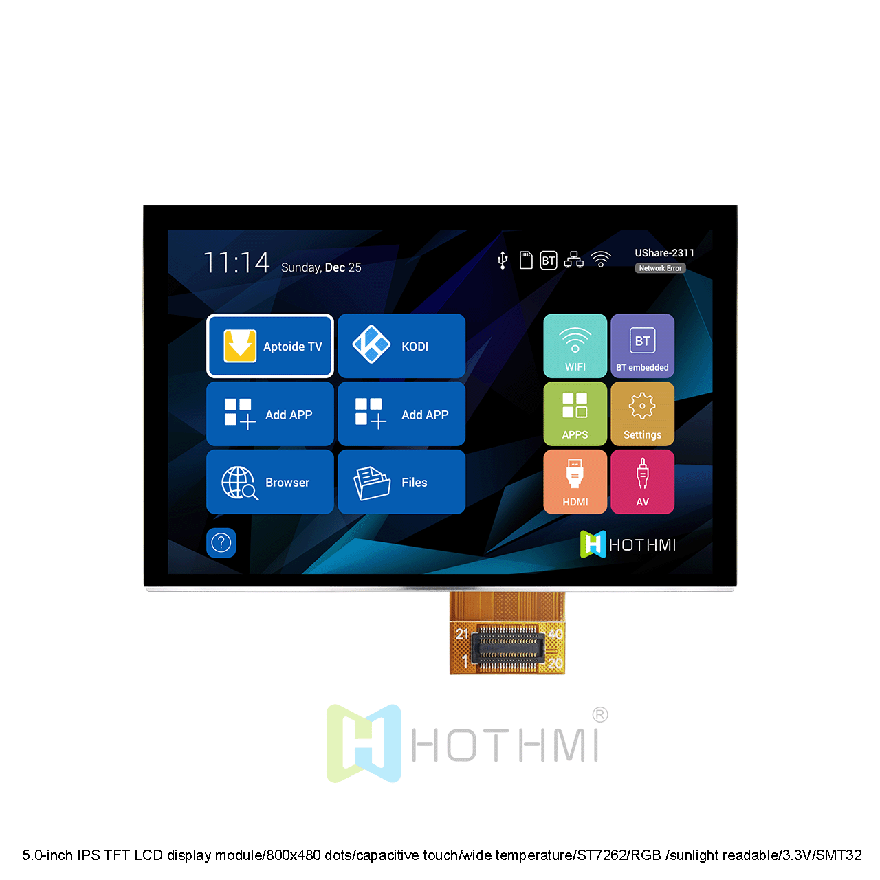
Step 1: Define the interaction. Determine whether the product needs single-touch, multi-touch or gesture control, and confirm that the controller and software support the required behavior.
Step 2: Define the cover. Specify the cover material, thickness, shape, surface treatment and printed area.
Step 3: Check the host system. Verify the touch-controller interface, driver support, power requirements and connector pinout.
Step 4: Confirm the display fit. Align the touch panel with the display active area and front-panel opening. Check edge clearances and cable routing.
Step 5: Validate the complete product. Test touch performance with the actual enclosure, cover, host board and intended operating environment.
The website lists capacitive touch structures including G+G, G+F, G+FF, P+G and P+F. The appropriate structure depends on the specific product and design requirements.
Selected products support changes to dimensions, shape, thickness, printed border and surface treatment. Confirm feasibility against the required size and structure.
Potentially, but compatibility depends on display dimensions, active area, touch controller, mechanical fit and connection method. Share the display model and drawings for evaluation.
Selected products support cable and connector-related customization. Provide the pinout, connector type, cable length and exit direction.
Provide the display model or size, cover drawing, touch structure, controller/interface, surface treatment, quantity and application.
Send HOTDISPLAY your cover-glass drawing, target display, touch requirements and host-controller details. We can help identify suitable products and review the customization options for your design.
What did our happy clients say?